How To Make CAT5e Patch Cables
Step 1: Before we start building a patch cable, you will need to cut a length of stranded Cat5e. When cutting the length, you should make sure to measure. Nothing is worse than the patch cable you just built being an inch too short for your application.
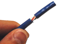
After cutting the desired length, we will start building our cable by stripping back approximately 1 inch of the jacket. We have a variety of tools.
When striping back the jacket, make sure that the depth of your stripper is set deep enough to cut the jacket but not so deep that it nicks the conductors. If you do nick the conductors while stripping the cable, the cable may work fine at first, but after time the conductors will break, or even worse, begin to short out.

Step 2: Now that we have the jacket stripped back, we'll want to separate and straighten the pairs. We'll start by pulling the first pair and the last pair to their respective sides (Orange to the left and Brown to the right). Untwist these pairs making sure not to untwist the cable any further than you've stripped back the jacket. Now we'll split the green pair. Pull the white/green conductor to the left and the green conductor to the right. This leaves you with the blue pair in the middle. Untwist the blue taking care to ensure that the white/blue conductor is on the left and the blue conductor on the right.
Note: Normally, it would be unmentionable to untwist the Cat5e pairs, except when building patch cables. It would be almost impossible to insert the conductors into the proper connector locations without untwisting. (Keep in mind you want to keep as much of the twist of each pair intact to meet performance standards.)


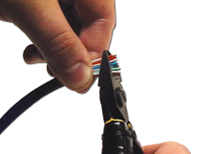
Step 3: Now that we've separated and straightened the pairs, we need to arrange the conductors in the proper order according to which wiring standard you are using. For this example, we will be wiring via the 568-B standard (most common in patch cables). Please consult the pin-out for the proper color codes. After you have the wires arranged, place them tightly together, as shown in the picture to the right. Once this is done, verify that the wires are still in the proper order and continue to step 4.

Step 4: Now, we need to trim the conductors down to fit into the RJ45 connector. While trimming, make sure you make an excellent clean cut at a 90-degree angle about 1/2 of an inch from the end of the jacket. If you fail to make a straight cut, some of the conductors may not reach the connector contacts. If you cut the conductors too short, again, they will not make contact. If you leave the conductors too long, when crimping the connector, the jacketing will not be gripped, leaving the strain on the conductors. This is not a good situation! For proper trimming, hold the wires securely just at the end of the jacket, as shown in the picture to the left. Be sure to keep the conductors in the proper order.

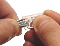
Step 5: Our Cat5e patch cable is almost done. While still holding the cable firmly, we now need to place the conductors into their proper location in the RJ45 Cat5e Modular Connector. Hold the RJ45 modular plug with the contacts facing up (towards you) and carefully insert the conductors in their proper locations. Apply a moderate amount of force to properly seat the wires against the contacts in the connector. When the wires have been correctly inserted into the RJ45 modular connector, observe the tip. As illustrated in the picture to the left, you should be able to see the end of each conductor, indicating that the conductors were fully inserted. Also, take note of the colors. All whites should be on the top and all the colored conductors on the bottom. Once this is achieved, continue to Step 6.
Update 10/03/2007:
Many customers have reported that they find Cat5e Connectors with load bars much easier to use during the termination process. The load bar is used to align the conductors into the proper order and hold them in place during insertion.

Step 6: Carefully insert the assembly, which you have just completed into a modular crimping tool, taking care to verify the conductors stay fully inserted. When crimping the connector, use the full stroke of the crimp tool so that the contacts properly "bite" into the conductors. After you have completed the crimp, take the time to look at the connector, and make sure all the pins were crimped and that they made good contact with the conductors.

Step 7: If you are building a straight-through (standard) Cat5e patch cable, terminate the opposite end by repeating this process from step one. If this will be a cat 5 crossover cable, return to step one and continue, however, terminate the other end of the cable using the wiring scheme that you did not use for the first end. Terminating one end with 568-B and the other with 568-A creates a crossover cable. If it is a straight-through cable you are making, use the same wiring scheme for both ends.

Step 8: That's it! Use a tester to test for continuity, and your DIY Cat 5, 5e patch cable is complete.
Note: If the cable does not test positive for continuity cut the connector off and start over, or buy one of our pre-made or custom length patch cords.

